Hardware Platform: Low level code —(assembler)—> computer architecture —(digital design)—> CPU, RAM, chipset —(gate logic)—> elementary logic gates —> EE, physics, and hardware.
In programming we normally start with how to make a “hello, world” application. We would write this in a high-level programming language. This programming language would be rich with expressions, loops, data types, classes methods, and built-in operations. However, what is the underlying implementation of this? The underlying implementation is the “how” and the high-level programming language is the “what”.
Programming allows us to have multiple levels of abstraction that lets us forget about the “how”. Here I’m going to learn the “how” by traversing these levels. At each step we can take the last level as given, focus on the current level’s implementation, and test that it works and continue.
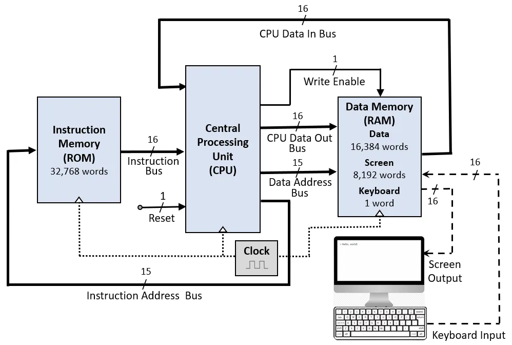
This series of blog posts will contain my reflections while teaching myself about elementary logic gates, ALUs, memory systems, low level programs, computer architecture, assemblers, and how to build a Hack Computer. This computer will have 3 components (ROM, CPU, RAM) and the final product can be connected to a keyboard and a display unit. I’ll teach myself this by going through the course Build a Modern Computer from First Principles.
Boolean logic
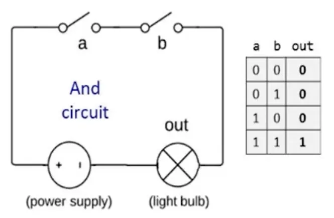
Boolean values can either be 0 or 1. We can perform boolean operations like And, Or, and Not:
| a | b | And |
|---|---|---|
| 0 | 0 | 0 |
| 0 | 1 | 0 |
| 1 | 0 | 0 |
| 1 | 1 | 1 |
| a | b | Or |
|---|---|---|
| 0 | 0 | 0 |
| 0 | 1 | 1 |
| 1 | 0 | 1 |
| 1 | 1 | 1 |
| a | Not |
|---|---|
| 0 | 1 |
| 1 | 0 |
With these boolean operations we can perform boolean expressions Not(0 Or (1 And 1)) = Not(0 Or 1) = Not(1) = 0. Using this knowledge we can make boolean functions like f(x,y,z) = (x And y) Or (Not(x) And z). These functions can be represented with formulas, truth tables, or canonical representations.
Boolean identities relate to mathematics. For example, a + b = b + a. Similarly (x And y) = (y And x). This is the commutative law. Also, associative laws, distributive laws, de morgan laws [Not(x Or y) = Not(x) And Not(y)], and more apply.
We can now apply these identities to boolean algebra to rearrange and rewrite expressions by laws. For example, Not(Not(x) And Not(x Or y)) = x Or y.
Boolean Functions
Any boolean function can be represented using an expression only using the operations And, Or, and Not. This is thanks to the finite world of boolean algebra. In fact, you can represent any expression using only And and Not operations.
Proof (de morgan law):
(x Or y) = Not(Not(x) And Not(y))
There is one operation that suffices to represent any expression, Nand. (x Nand y) = Not(x And y). It is the negation of x And y.
| a | b | Nand |
|---|---|---|
| 0 | 0 | 1 |
| 0 | 1 | 1 |
| 1 | 0 | 1 |
| 1 | 1 | 0 |
Proof:
If you can do Not and And, you can do everything. We can see that Not(x) = (x Nand x) and (x And y) = Not(x Nand y).
Logic Gates
A logic gate is a technique to implement boolean functions. I’m going to be using “gates” interchangeably with “chips” because we’re talking about physical devices that implement boolean functions. Examples can be elementary like Nand, And, Or etc. or composite like Mux, Adder, and more.
We see only the inputs and outputs and not the implementation. If you wanted to briefly understand it, you’d take a look at the documentation/interface/abstraction of the chip. The implementation is the “how” and the interface is the “what”. Think of chips as APIs where you could pass a request body (input) and receive a response (output) based on the chip’s inner functions (business logic/implementation).
Circuit implementations can realize these gates with electricity. The light bulb in a circuit being on/off would represent the output of a gate.
However, I will not be diving into physical implementations since that would be more aligned with electrical engineering and physics than computer science.
HDL
Hardware Description Language (HDL) allows us to simulate and test logic gates. Let’s take a look at how we’d write a Xor gate:
/**
 *  Exclusive-or gate: out = !(a == b).
 */

CHIP Xor {
    IN a, b;
    OUT out;

    PARTS:
	Not(in=a,out=na);
	Not(in=b,out=nb);
	And(a=na,b=b,out=c);
	And(a=a,b=nb,out=d);
	Or(a=c,b=d,out=out);

}
Steps for writing HDL usually follow the following steps:
- Look at the truth table and synthesize the boolean functions that generate an output of 1.
- Use this insight and come up with a gate logic diagram to build the boolean function with basic logic gates (comes with experience).
- Draw the boundary of the gate interface
- Draw the inner gate implementation with basic logic gates
- Tag signal lines with sensible names
- Implement the diagram using HDL
- Start by writing the stub version (interface) of the HDL file (comment and chip in/out)
- Finish the implementation (can be done in many ways)
HDL should be well documented and readable just like when we’re programming in any other language. HDL is a functional and declarative language. It is a static description of a gate diagram. Before using chip parts, you must know their interfaces. There are many HDLs out there with the most popular being VHDL and Verilog. Here’s a general survival guide.
Hardware Simulation
How do we know our HDL is correct? We can do so through hardware simulation. This can be done interactively, with test scripts, and with/without output and compare files.
The simulator allows us to debug through the logic gate architecture. You can load a chip, change the input pins, and calculate the output. Also, after calculating the output you can take a closer look at the internal pins.
Multi-Bit Buses
A bunch of bits together as one entity are sometimes termed as a bus. For example, if you wanted to add two 16-bit binary numbers you’d want to take two buses of 16-bits as inputs and a 16-bit number as an output. Buses can be composed from and broken into sub-buses. A 16-bit bus can be formed from two 8-bit buses.
Works Cited
- Nisan, Noam, and Shimon Schocken. The Elements of Computing Systems: Building a Modern Computer from First Principles. MIT, 2021.